Theoretical basics of the Scheiner-method
When trying to align a telescope correctly with or without polar finder (see menu points under 'Proceeding' - 'Alignment'), and to align the right ascension axis parallel to the Earth's rotation axis via the azimuth and pole height adjustment, alignment errors (e.g. when setting up the telescope) cannot always be avoided. Likewise, a clear view of Polaris is not given in every constellation.
The following errors, among others, are compensated for by the Scheiner-method:
- The telescope is not exactly aligned.
- The polar finder and the telescope are not exactly parallel (due to the installation).
- The orientation in the direction of Polaris is not exactly adjusted in the polar finder.
- Due to refraction in the earth's atmosphere the apparent North celestial pole is slightly higher than the true North celestial pole. [5]
(Dieser Fehler kann nur direkt im Zenit, dem Lot über dem Teleskop, ausgeschlossen werden, da dort die Lichtstrahlen senkrecht auf die Erdatmosphäre treffen.)
The misalignment of the rectascension axis with the North celestial pole ("pole error") is characterized by two components perpendicular to each other [5]:
- by the azimuth error and
- by the pole height error
Julius Scheiner (1858 - 1913) recognized that these two parts of the pole error show up in certain positions of the mount as a drift of a star exclusively in declination direction. Errors in the drive of the right ascension axis are therefore ineffective, because they have an effect only in the right ascension direction. Thus, in two different positions of the telescope, the azimuth error and the pole height error can be corrected independently. [5]
The procedures for achieving the two positions are explained below, and it is shown which procedure is to be preferred.
With the Scheiner-method, it should always be started with the correction of the azimuth error. Note: Theoretically, it is also possible to start with eliminating the pole height error. According to Julius Scheiner's original writings [5] however, a star in the East or West, which is at 6 h or 18 h, respectively, would have to be used for this purpose. (à declination 0° à Star is exactly on the East or West horizon). However, trees or other obstacles are often in the way at this position. In addition, the influence of refraction due to the low air masses would not be insignificant in this position.
The refraction error, generated by refraction of light in the Earth's atmosphere, increases toward the horizon and causes the object of observation to be elevated near the horizon. [7]

Effect of refraction when observing an object on the horizon [9]
The following table from the „Handbook for star friends“ shows the refraction, when slewing from the zenith towards the horizon: [2]
| Mean refraction according to Bessel's table (760 mmHg, 0°C) | |||||||||||||
| 0° | 10° | 20° | 30° | 40° | 50° | 60° | 70° | 75° | 80° | 85° | 88° | 89° | 90° |
| 0‘ | 0‘11‘‘ | 0‘22‘‘ | 0‘35‘‘ | 0‘51‘‘ | 1‘11‘‘ | 1‘45‘‘ | 2‘45‘‘ | 3‘42‘‘ | 5‘31‘‘ | 10‘15‘‘ | 19‘70‘‘ | 25‘36‘‘ | 36‘38‘‘ |
Julius Scheiner was aware of this effect when he published his method and added that the influence of refraction must be eliminated. [1]
A very good study on the subject of refraction can be found in a publication of the Astronomische Arbeitsgruppe Laufen e.V. [1]. In this, it was shown by means of measurements that the refraction error is larger than the error that occurs when a star is used that is 20° to 30° above the horizon in the East or West.
For these reasons, the pole height adjustment can never be performed exactly, regardless of being at the horizon or 20° to 30° above it. If starting with the pole height, additional iterations of the azimuth and pole height adjustment are necessary in any case. [8]
Basics of the azimuth error
Before starting with the Scheiner-method and the correction of the azimuth error, the telescope must be brought into the home position and the tracking must be started. This procedure can be looked up in the menu item 'Proceeding' - 'Alignment' - 'Aligning with the Scheiner-method'.
To correct the azimuth error Julius Scheiner describes in his original writings [5] that the telescope should be pointed to a star which is in the zenith on the meridian (declination = pole height) (see menu point 'Components' - 'Mount and tripod'). This is to minimize the refraction error and the deflection error of the mount. [5]
Along the meridian only the azimuth error causes a drift in declination direction. [4].

Effect of azimuth and pole height errors on declination along the meridian [4] (translated)
In many instructions for the Scheiner-method it is pointed out that a star at the celestial equator (declination = 0°) and not at the zenith should be used. This increases the refraction error somewhat, but the stars travel a longer distance along the celestial equator for the same amount of time.
For distances covered farther, the misalignment has a more significant effect and can be corrected more quickly.
Along the latitudes of Germany (48° - 54°) a guide star on the celestial equator is still more than 45° above the horizon. Refraction is not yet overly influential in this range.
But really correct would be the choice of a star in the zenith on the meridian.
The following explanations for the correction of the azimuth error can be applied to a guide star on the celestial equator as well as to one in the zenith.
It is started by moving the telescope along the meridian line (North-South line) to the celestial equator (alternatively zenith).
To travel along the meridian line, the counterweight rod is aligned horizontally in the East-West direction starting from the home position by means of the right ascension axis.
Note: If a star in the East is approached during the later pole height correction, the tube should be on the West side. And vice versa: For a star in the West, the tube should be on the East side. This avoids a later swinging of the tube from one side of the mount to the other, because the counterweight rod is already on the "right" side. Otherwise, the counterweight rod would bump against the tripod. [8]
The celestial equator is found by slewing the telescope 90° from the home position via the declination axis. Likewise, the tube could be aligned horizontally to the South and then the telescope slewed upwards by '90° - pole height'. If a guide star at zenith is to be used for adjustment, the telescope aperture is slewed perpendicularly upwards.
Arrived at the position of the celestial equator, a suitable guide star is to be searched for. It should be in a range of approx. ±1.5° around the meridian/zenith and ±5° around the celestial equator. [7]

Selection of the star near the meridian and celestial equator
The crosshair eyepiece can then be centered on this guide star. It is helpful if a magnification corresponding to the optical aperture (combination of crosshair eyepiece and Barlow lense) is selected (approx. 1.25 - 1.5 x aperture in mm). A relatively high magnification benefits the accuracy of the procedure. [8]
Afterwards, the horizontal line of the crosshair eyepiece is aligned parallel to the current movement of the right ascension axis. Using the eyepiece aligned in this way, the misaligned tracking movement of the mount, which has not yet been adjusted, can be tracked very well.
To perform this step, the crosshairs are centered directly on the selected guide star. Now the telescope can be tilted along the right ascension using the keys on the hand control box. The eyepiece is rotated so that the guide star moves along the horizontal line of the crosshairs. It should be noted that the declination axis is fixed, as it must not be adjusted. In this case, it is not yet necessary to pay attention to the image orientation by accessories.
Note: Since the direction is South, East is left and West is right! The meridian line extends from the star across the observer in the direction of North. North and South are therefore not interchanged when just looking at the sky.
 Parallel alignment of the crosshair eyepiece to the celestial equator (view to the South, therefore West is on the right) Parallel alignment of the crosshair eyepiece to the celestial equator (view to the South, therefore West is on the right) |
|
Since the slewing motion of the right ascension axis is much faster than the motion of the Earth's rotation, the crosshair eyepiece is thus aligned with the star that is almost "fixed" in the sky. Here, the azimuth or pole height error is not yet corrected. The procedure only serves to align the eyepiece.
If the procedure was not exact and fast enough (the star has meanwhile "moved on" slightly on the celestial sphere due to the earth's rotation), it is possible that this procedure has to be repeated. The more precisely the crosshair eyepiece is aligned, the better the polar alignment will be.
Once the crosshair eyepiece has been successfully aligned, it must not be twisted again until the end of the Scheiner-method. [8]
After that, the correction of the azimuth error can be started.

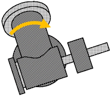
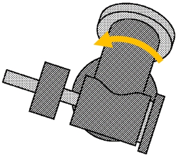
Influence of an incorrect azimuth direction on the tracking of a parallactic mount [6] (translated)
In the illustration of case 1, it can be seen that the mount is rotated too far to the East via the azimuth adjustment. If you look at the mount from above, you can see a counterclockwise rotation. The tracking (solid line, red arrow) therefore slowly drifts South, so that the guide star in the eyepiece appears to move North. The azimuth adjustment must therefore be rotated clockwise (yellow arrow) back towards the meridian when viewed from above. [6]
In the illustration of case 2, the mount is rotated too far to the West via the azimuth adjustment. When looking at the mount from above, a clockwise rotation can be seen. The tracking (solid line, red arrow) therefore drifts slowly to the North, so that the guide star in the eyepiece appears to move to the South. The azimuth adjustment must therefore be rotated counterclockwise (yellow arrow) back towards the meridian when viewed from above. [6]
As shown in the pole height error illustration, in this position the pole height error does not affect the declination drift. However, due to inaccuracies in the drive, mechanical deflections or atmospheric refraction, it is possible that a slight drift can also be seen in the East/West direction.
This drifting is indicated in the following tables, but is of no further importance for the correction of the azimuth error, since such errors are later compensated by a possible tracking control (autoguiding).
To rotate the mount in the correct direction around the azimuth axis when using accessories, the image orientation must be taken into account in this case (see menu point 'Components' - 'Telescope types' - 'Table for image orientation')
Setup A:
A Refractor-, Newtonian- or Schmidt-Cassegrain-Telescope with eyepiece only is used. → The image is upside down and laterally reversed (is rotated 180°).
Setup B:
A Refractor- or Schmidt-Cassegrain-Telescope with zenith mirror / zenith prism is used. → The image is upright, but laterally inverted (mirrored about the vertical).
It is important to ensure that the aperture of the zenith mirror / zenith prism points upwards and is not adjusted during the pole height correction, otherwise the images in the following table will no longer match those in the crosshair eyepiece.
The image orientation depends on the rotation of the mirror / prism in the sleeve. If the mirror / prism is rotated, the image field rotates in the same direction. Therefore, the use of a mirror / prism should be avoided if possible when using the Scheiner-method. [3]
Setup C:
A Refractor-, Newtonian- or Schmidt-Cassegrain-Telescope with Amici prism / Erecting lense (for Newtonians) is used. → The image is upright and laterally correct (thus it corresponds to the view with the naked eye).
The following table provides instructions for the use of accessories.
Note: By looking South, East is to the left and West is to the right with the naked eye.
 Star movement in the aligned crosshair eyepiece during azimuth correction |
|
View through a telescope to the South during azimuth correction
| Setup A (with eyepiece) | Setup B (with zenith mirror / zenith prism) | Setup C (with Amici prism / Erecting lense (with Newtonian)) | |
| A slight drift in the East-West direction does not require further attention | |||
| Case 1 mount is rotated too far to the East; | 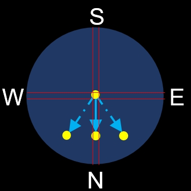 |  |  |
| Case 2 Mount is rotated too far to the West; |  |  |  |
The most practical procedure is to first make a rough angle change around the azimuth axis, so that the adjustment is consciously made a little beyond the target. This makes it easier to see whether the adjustment was really made in the right direction, and the next test step (coming from the other side) can be used to iteratively approach the correct position. After each step, wait a few minutes to see in which direction the star moves out of the image and correct accordingly. This process is repeated until the star no longer moves out of the image vertically to the tracking direction, but can only be found in the center along the horizontal line of the crosshair eyepiece. For astrophotography, it is usually sufficient if the star remains in the center of the image for about 10 to 20 minutes with only an almost imperceptible deviation. [7]
Basics of the pole height error
Note: If the attempt to align both the tripod horizontally by using a digital spirit level and the latitude via the pole height to one decimal place is successful, the somewhat error-prone pole height correction can be dispensed with).
Scheiner describes in his original papers [5] that to correct the pole height error it is useful to use a guide star directly on the East or West horizon. (Whether the East or the West is chosen depends in each case on the better viewing direction).
At this position only the pole height error causes a drift in declination direction. [4] The azimuth error does not affect the declination drift at this position.

Effect of azimuth and pole height errors on declination along the East-West direction. [4] (translated)
For the reasons mentioned in the first part, a star in the East or West 20° to 30° above the horizon near the celestial equator is chosen. This greatly reduces the refraction error, even though the slightly more inclined position introduces another small error.
To approach this position in the East or West, the right ascension axis of the telescope is released (or the keys of the hand control box are used), and the telescope is slewed along the celestial equator to the corresponding position in the East or West. Using the declination axis, a suitable star can now still be positioned in the center of the crosshair eyepiece.
Note: The crosshair eyepiece is tilted over the right ascension axis due to the rotational movement and must also remain in this position.
The guide star should be a maximum of ±5° from the celestial equator [7]
 Selection of a star in the East near the celestial equator | 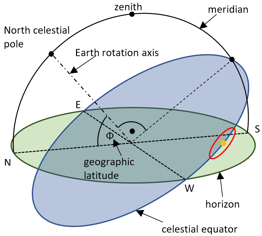 Selection of a star in the West near the celestial equator |
Once the guide star has been centered, the correction of the pole height error can be started.

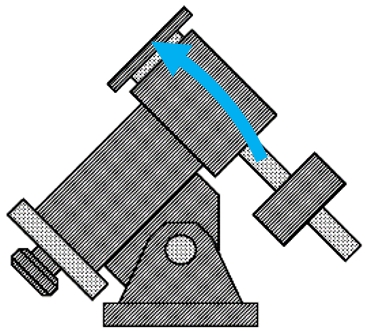
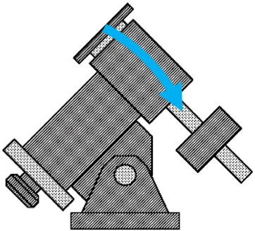
Influence of an incorrect pole height in the East on the tracking of a parallactic mount [6] (translated)
In the illustration of case 1E it can be seen that the pole height is aligned too flat. The tracking (solid line, red arrow) therefore drifts to the North, so that the guide star in the eyepiece appears to move to the South. The pole height must therefore be set steeper (blue arrow). [6]
In the illustration of case 2E, the pole height is aligned too steeply. The tracking (solid line, red arrow) therefore drifts to the South, so that the guide star in the eyepiece appears to move to the North. The pole height must therefore be set flatter (blue arrow). [6]

Influence of an incorrect pole height in the West on the tracking of a parallactic mount [6] (translated)
In the illustration of case 1W it can be seen that the pole height is aligned too flat. The tracking (solid line, red arrow) therefore drifts to the South, so that the guide star in the eyepiece appears to move to the North. The pole height must therefore be set steeper (blue arrow). [6]
In the illustration of case 2W, the pole height is aligned too steeply. The tracking (solid line, red arrow) therefore drifts to the North, so that the guide star in the eyepiece appears to move to the South. The pole height must therefore be set flatter (blue arrow).[6]
In order to rotate the mount in the correct direction around the pole height axis when using accessories, the image orientation by accessories must be considered again (see menu item 'Components' - 'Telescope types' - 'Table for image orientation').
Setup A:
A Refractor-, Newtonian- or Schmidt-Cassegrain-Telescope with eyepiece only is used. → The image is upside down and laterally reversed (is rotated 180°).
Setup B:
A Refractor- or Schmidt-Cassegrain-Telescope with zenith mirror / zenith prism is used. → The image is upright, but laterally inverted (mirrored about the vertical).
It is important that the aperture has not been adjusted since the azimuth correction, otherwise the images in the following tables will not match those in the crosshair eyepiece.
The image orientation depends on the rotation of the mirror / prism in the sleeve. If the mirror / prism is rotated, the image field rotates in the same direction. Therefore, if possible, the use of a mirror / prism should be avoided when using the Scheiner-method. [3]
Setup C:
A Refractor-, Newtonian- or Schmidt-Cassegrain-Telescope with Amici prism / Erecting lense (for Newtonians) is used. → The image is upright and laterally correct (thus it corresponds to the view with the naked eye).
1. View to the East:
Due to the rotational movement about the right ascension axis, the crosshair eyepiece is tilted and has the orientation shown below when looking through it.
Note: By looking South, to the naked eye, East is to the left and West is to the right.
 Star movement in the crosshair eyepiece during pole height correction with a guide star in the East |
|
View through a telescope towards West during pole height correction
| Setup A (with eyepiece) | Setup B (with zenith mirror / zenith prism) | Setup C (with Amici prism / Erecting lense (with Newtonian)) | |
| Case 1O pole height is too flat |  |  |  |
| Case 2O pole height is too steep |  |  |  |


2) View to the West:
Due to the rotational movement about the right ascension axis, the crosshair eyepiece is tilted and has the orientation shown below when viewing the guide star.
Note: By looking South, to the naked eye, East is on the left and West is on the right.
 Star motion in the crosshair eyepiece during pole height correction with a guide star in the West Star motion in the crosshair eyepiece during pole height correction with a guide star in the West |
|
View through a telescope towards West during pole height correction
| Setup A (with eyepiece) | Setup B (with zenith mirror / zenith prism) | Setup C (with Amici prism / Erecting lense (with Newtonian)) | |
| Case 1W pole height is too flat | 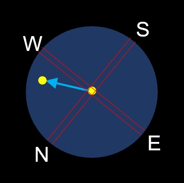 |  |  |
| Case 2W Pole height is too steep | 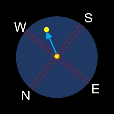 |  |  |
As with azimuth correction, it should be started with a larger change in angle, so that it is consciously adjusted a little beyond the target and iteratively approached to the correct position. This process is repeated until the star no longer moves out of the image vertically to the tracking direction, but can only be found in the center along the East-West line of the crosshair eyepiece. For astrophotography, it is usually sufficient if the star remains in the center of the image for about 10 to 20 minutes with only an almost imperceptible deviation. [7]
If you now return to the starting point of the position for the azimuth correction and observe a star in South direction, it may be that the azimuth must be slightly corrected again. This procedure must then also be repeated for the pole height. [3]
Sources:
[1] http://astronomy.utfs.org/forum/polhoehe.html
[2] http://astronomy-peter.de/tips-and-tricks/par-mount.html
[3] http://www.astronomie.biz/montierungen/download/scheiner-klassic.pdf
[4] http://www.astronomie-papenburg.de/Ausrichten_einer_parallaktischen_Montierung.pdf
[5] https://de.wikipedia.org/wiki/Scheiner-Methode
[6] https://www.baader-planetarium.com/de/downloads/dl/file/id/83/product/1057/die_pdf
[7] https://www.nies.ch/doc/astro/scheiner.pdf
[8] https://www.sternfreunde-muenster.de/pdf/andromeda20071.pdf
[9] Sciencia58, CC BY-SA 4.0, via Wikimedia Commons